Do you have plans for a product that would benefit from sheet metal construction? NeuronicWorks has over a decade of experience designing with sheet metal across multiple industries, including automotive, medical, and transportation, to name just a few. Contact us today to find out how NeuronicWorks can help you bring your sheet metal visions to life.
Process and Best Practices
Continuing in our series on Design for Manufacturing, this time we’re taking a look at sheet metal design. As the name implies, this involves designing components and assemblies using formed sheets of thin metal.
Sheet metal is my favourite construction material as a designer, and I like to think of it as engineering origami. The material itself is relatively weak and malleable (akin to the paper in origami), but with careful design it can be bent and folded into something robust, lightweight, and easy to manufacture. The fact that a sheet metal component derives its strength from geometry makes sheet metal design slightly trickier; however, once you start, you’ll quickly fall in love!
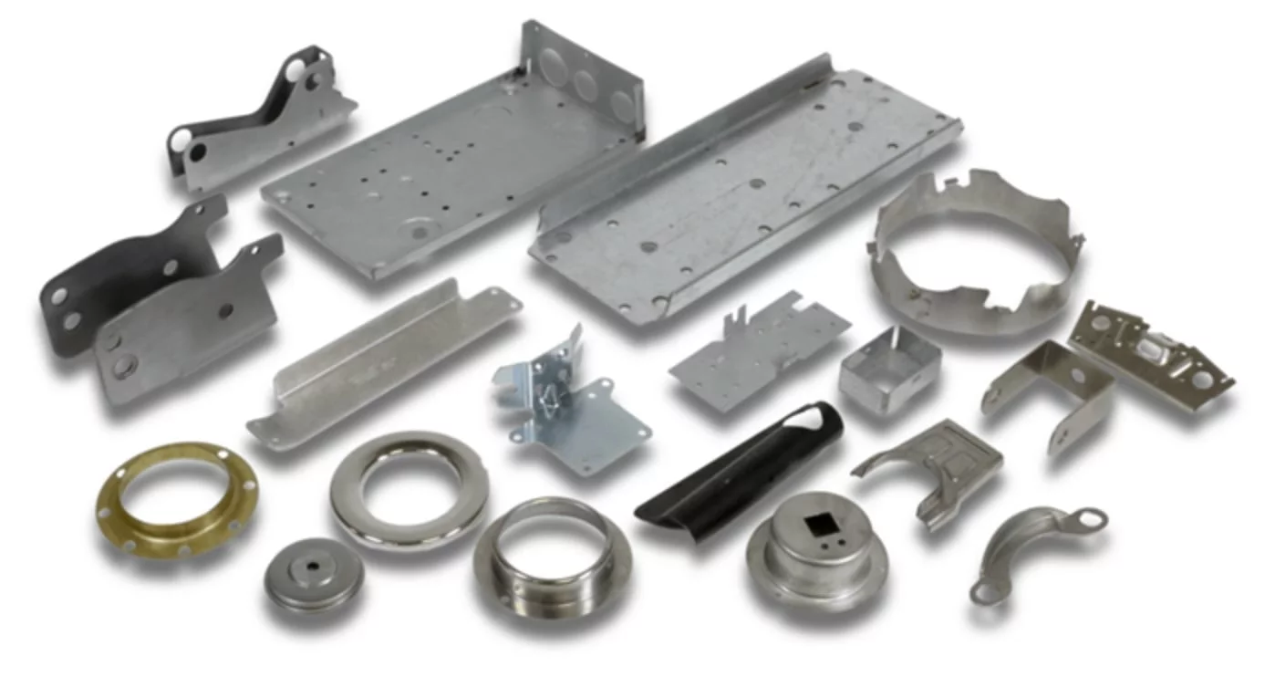
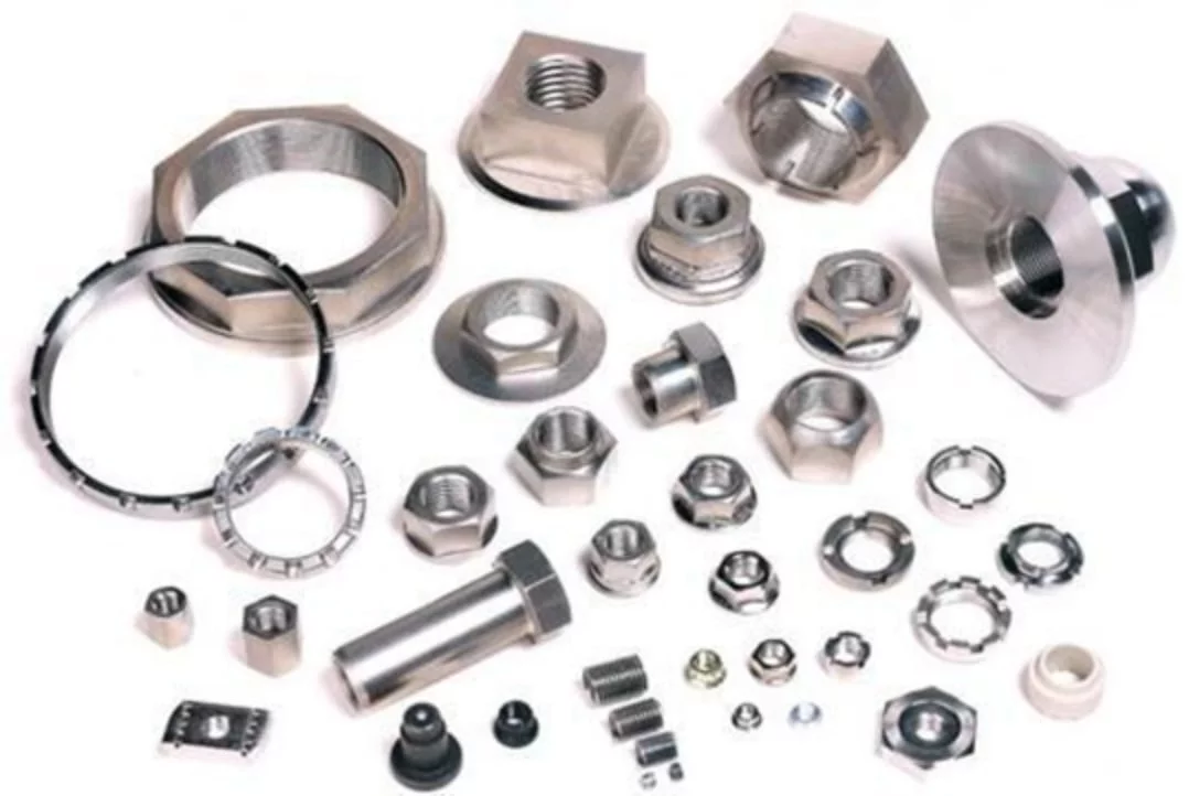
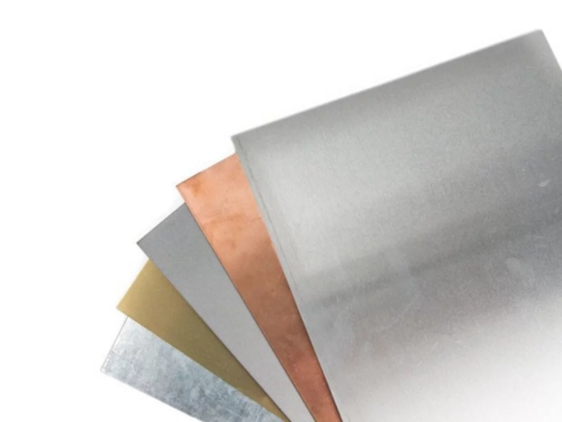
Figure 1: Sample Sheet Metal Components. Above Image Source
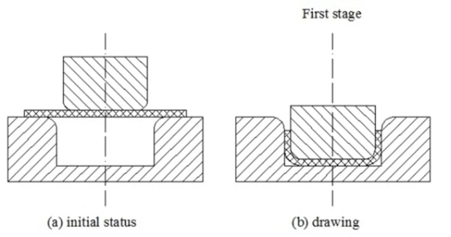
There are two main ways that sheet metal components can be manufactured: bending or stamping. Both involve taking a flat piece of thin metal and forming it into a final shape, but the process by which they do this varies immensely. In stamping, the sheet is inserted into large presses, which stamps the metal in a series of forms.
The immense pressure of these presses forces the sheet into the form’s shape, and a finished component is ejected from the end of the press.
Bending, on the other hand, involves cutting the metal to shape before it’s placed in a bending machine, where one bend is put on the part at a time.
As it is much more manual, bending is significantly slower and laborious. However, it requires little in the way of tooling. Stamping can run thousands if not hundreds of thousands of components very quickly without much operator interaction, the trade-off being that it requires a very expensive stamping die, mated to costly presses.
In general, low volumes of 1-10,000 parts tend towards bending, where 10,000 and up tend towards stamping (though, of course, there are exceptions). The design considerations for these two processes are quite different, as much more complicated geometry is possible with stamping dies. Therefore, this article will focus solely on bending.
Sheet Metal Manufacturing
Before you start designing with sheet metal, it’s important to study the actual process by which the parts get made. It essentially consists of four steps (each of which is discussed below): Blanking, Forming, Inserts, and Finishing.
Blanking
In sheet metal, all components are cut from sheets of bare metal, usually measuring 4x8’. The process of cutting out the bare shape of the component is called blanking. This blank can then be taken and bent or formed at later stages. There are numerous ways to cut a blank, including waterjets, shears, plasma cutters, etc. however, the most common are laser cutters and CNC turret punches.
A laser cutter uses a very high-powered laser to cut shapes into the metal, providing a quick and easy method to create complicated cut-outs. The heat generated during this cutting, however, can be a significant hinderance. Coated materials (such as painted and galvanized materials) are difficult to cut via a laser, as they create noxious gasses when cut. The heat generated can also create a heat affected zone (HAZ) around the edges, making welding more difficult for some materials.
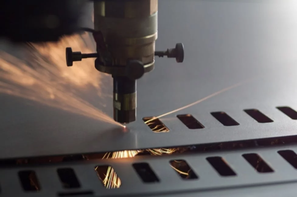
Turret punches, on the other hand, use a punch and die to create standard cut-outs in the metal. This process is extremely fast and creates no HAZ. However, using a punch restricts the geometry that can be cut to the tooling stocked in the machine.

In general, laser cutters are used for smaller production runs and/or parts with intricate patterns. Keep this in mind when you design your components and be sure to reach out to your local sheet metal shop to discuss their stocked tooling should you decide a turret punch is the right way to go.
Forming
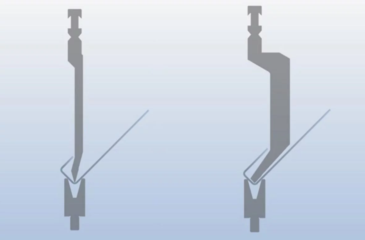
In general, for sheet metal, there are two forming categories, bending and pressing. Bending is likely the one that comes to mind when you think of sheet metal—it’s the addition of flanges to the edges of a sheet metal part. These are usually created in a brake press, a large vertical press that applies direct pressure to the bend line causing the material to bend around that point.
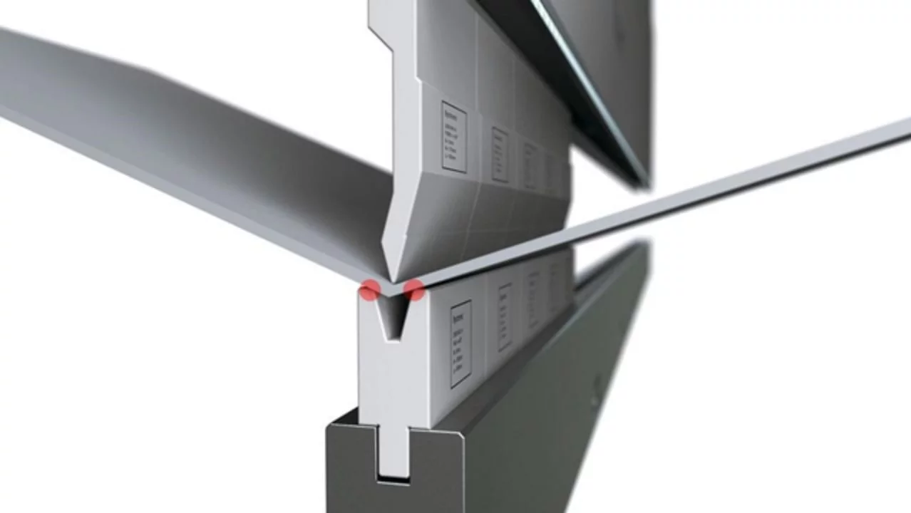
Using specialized tooling like hem, gooseneck, or sash tooling will net you tight compound bends that you may not have thought possible. Pressing, or forming, is akin to small scale stamping. An upper and lower form are placed in the press brake, with the press brake applying a large amount of pressure to create that form in the metal. Common forms include jogs and louvers; however, a vast array of shapes can be created using this method. As with stamping, the limitation here is the tooling. Custom tooling can be very expensive for a low volume production run, so be sure to talk to your supplier about their stocked tooling before you get too deep in the design process.
Inserts
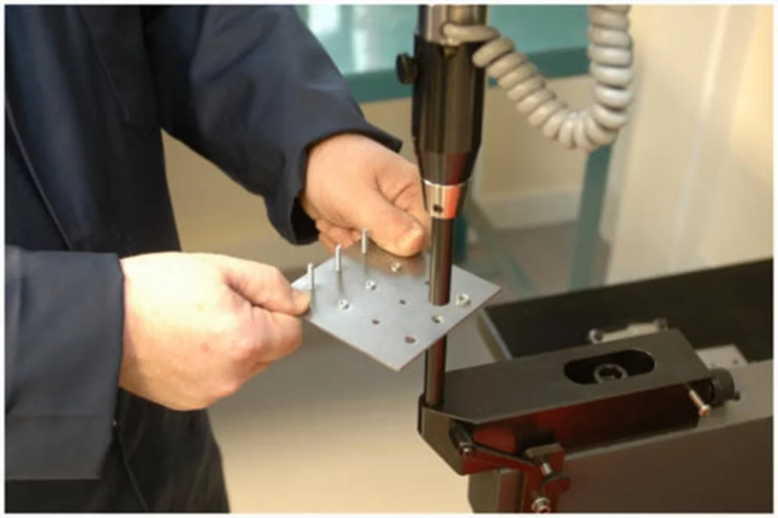
When making a structure from sheet metal, fasteners will be required to complete assembly, or to allow components to be mounted. Using sheet metal inserts allows these fasteners to come pre-installed. This saves time during assembly and lowers the number of components on your assembly BOM.
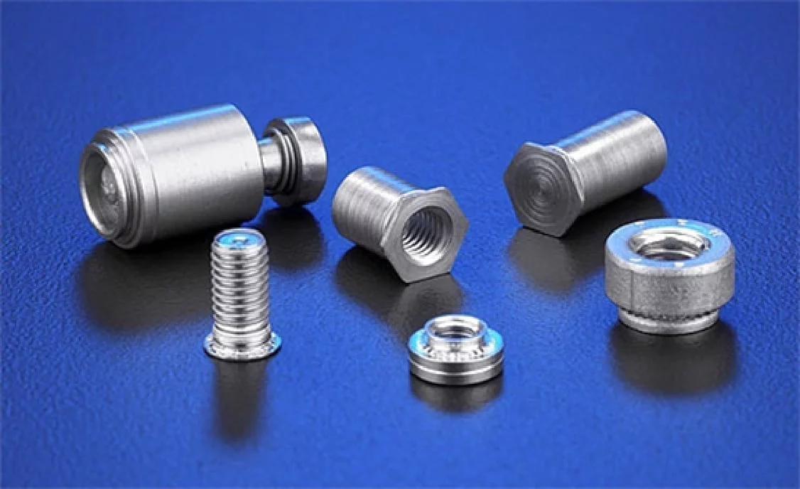
Inserts can be affixed before or after forming, depending on the components’ geometry and operator access. The most common type of insert is the PEM insert, or self-clinching insert. These inserts have a special head design that (when pressed into the correct sized hole) cold form the sheet such that material flows into specially designed ribs on the insert. The insert locks into place, resisting torque and some degree of pull-out. PEM inserts come as nuts, studs, pins, standoffs, zip ties mounts, and more, allowing for design freedom. In case you couldn’t tell, we at NeuronicWorks are huge fans of PEM inserts and their added efficiency.
PEM inserts aren’t the only game in town, however. You can get Rivnuts (rivet-nuts), which install in virtually any through-hole, or you can get weld nuts/studs.
Rivnuts are relatively cheap and can be installed even in blind holes. They take up the most space, however, and have limited material options. Weld nuts/studs are the strongest, but are difficult to accurately position on the component and carry all the same disadvantages as the welding process they are being affixed with.
The Finishing Touches
After blanking, forming, and the addition of inserts, the component is mostly complete, just requiring welding (if applicable) and finishing. Though part of the process, they are not unique to sheet metal, so we’re going to ignore them for now. However, it is important to note that as a thin uncontrolled material, sheet metal weldments are highly susceptible to warpage during welding (especially materials with low thermal conductivity like stainless). Keep this in mind during your design process, and make notes in your drawing specifying the weld order (ideally specifying shorter welds, distanced apart) should warpage be an issue.
Sheet Metal Design
Once you understand how sheet metal parts are created, you can begin designing sheet metal components. Starting out, you need to define three key parameters: material, thickness, and bend radius. Not all materials come in thin sheets, and of those materials not all are suitable for bending. The most common sheet materials are aluminum, stainless steel, cold-rolled steel, and copper. Care must be taken, however, to ensure that the chosen material grade is suitable for forming. Even within a given material, not all grades can be formed.
Once the material is selected, the material thickness is the next parameter to be defined. Material thickness in sheet metal is an easy way to trim significant amounts of weight and reduce material cost. Since much of a part’s strength comes from geometry, you can often get away with thinner material than you originally thought, and trimming thickness is often much more effective (both from a cost and weight perspective) than adding cut-outs. Be sure to stick to common thicknesses of sheet and reach out to your sheet metal suppliers to know their commonly stocked gauges. Lastly, determine the bend radius. Specifying too small a bend radius can cause a host of problems due to the amount of material flow necessary during bending. The wrong bend radius can cause tearing, necking, or fracturing, which is to be avoided at all costs. We always recommend speaking with your sheet metal supplier about their stocked tooling and recommended radii. In general, however, your inner bend radius should be greater than or equal to your material thickness.
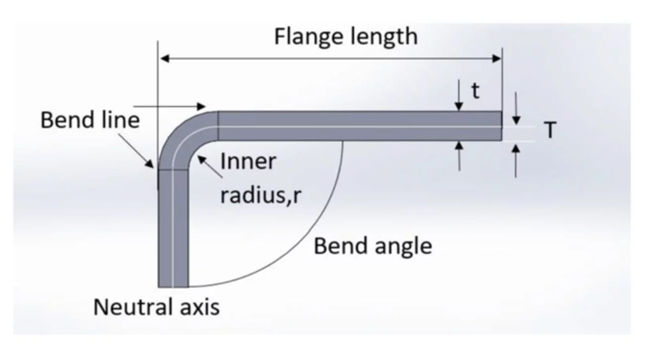
Once you’ve defined these three parameters, you’re good to start designing with sheet metal! As with all construction methods, there are many things to watch out for that can cause cosmetic or functional defects in your parts. For the most part, they can be caught with simple design reviews. However, some of the most common mistakes designers make (us included sometimes!) are discussed below.
Bends
Minimum Height
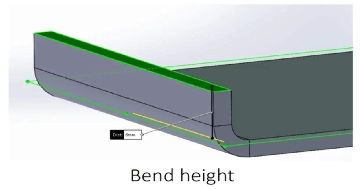
The length of a flange needs to be long enough that it can be supported in the die and have enough strength to maintain straightness. The minimum bend height can be calculated with the following formula:
Bend height=2*thickness+bend radius
Failure to follow this will cause varying bend quality, and likely some localized deformation.
Bend Relief
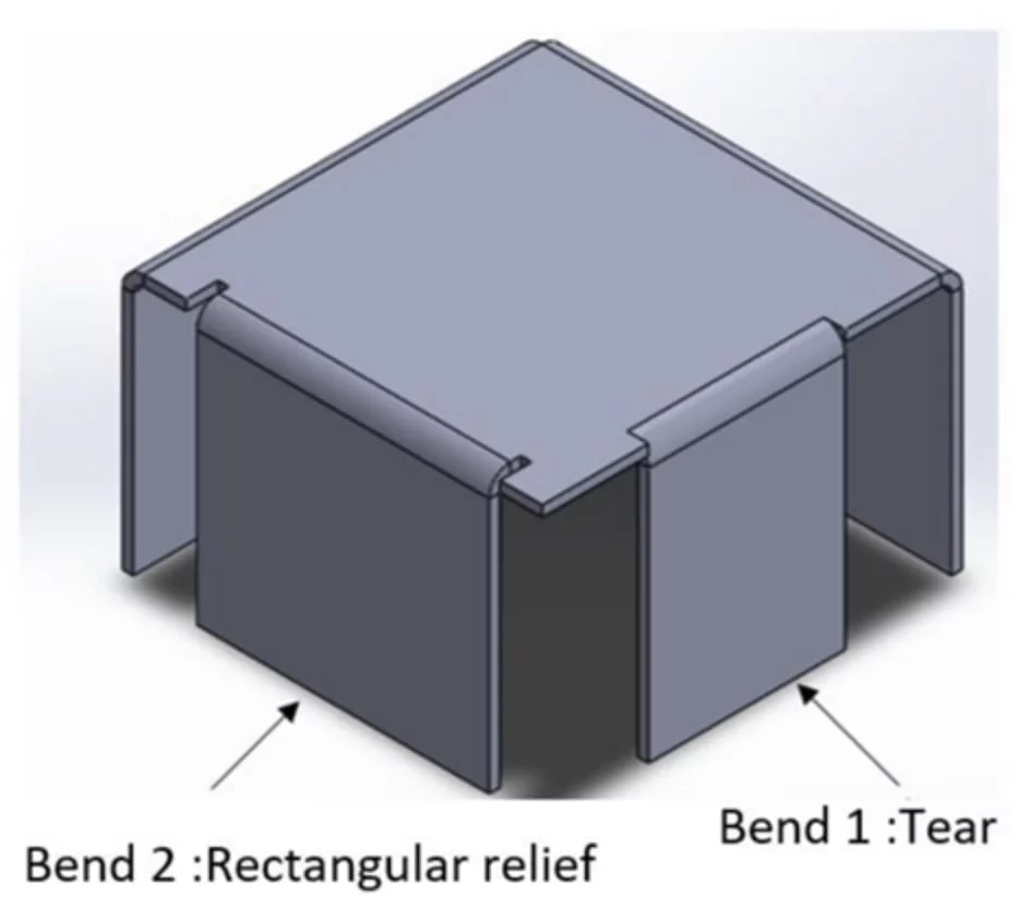
● When a bend meets another bend (at a corner for example) or when it is in the middle of an edge, some material needs to be removed. This leaves space for the material to flow, and so that the metal is not rubbing during bending. To do this, you can use the built-in relief functions in your CAD software, or simply cut out areas next to your bends for relief.
Cutouts
Cutouts near bends
● As material flows during bending, placing a cut-out too close to a bend will cause that cut-out to deform. In general, the following formula should be applied to determine the distance from the outside edge to a cut-out:
Distance=2.5*thickness+bend radius
Hole Sizes
● A common rule of thumb is the minimum hole size should be the thickness of the material. Though we don’t run into this rule very much (as we laser cut most things, and don’t usually use holes that small), it is worth remembering especially if you plan to use thin material and CNC turret punches.
Countersinks
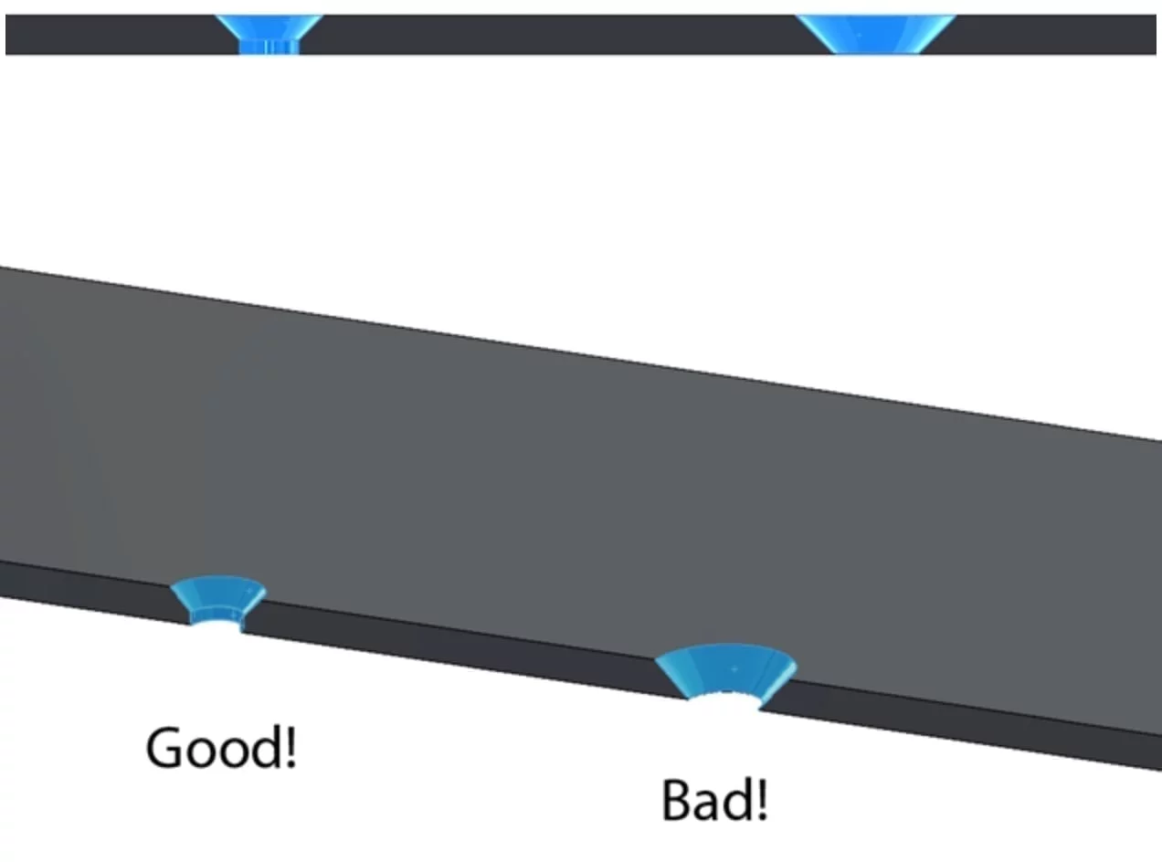
● Due to the thin nature of the material, machining countersinks can weaken the material too much. A common rule of thumb is the countersink depth should be no more than 0.6 times the material thickness.
Fillets
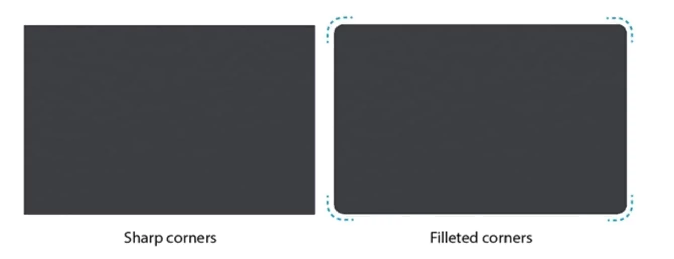
● Fillets are always a good idea, but in sheet metal they are especially important. Cut sheet metal can be incredibly sharp and adding fillets wherever possible will help keep your assemblers, and the sheet metal shop’s fabricators, safe. If using a turret punch you may also have to put fillets into some geometry to make it fabricable. Talk to your supplier to confirm what tooling they carry or recommend.
Now that you know how sheet metal parts are made, as well as the common challenges that arise, you know what to look for in a quality sheet metal design.
