Do you have a great idea doodled on a napkin which you would like to validate and realize? Do you want to know how it would look as a 3D model? Our team can help you turn your paper scribblings into real, validated ideas.
Top 10 Tips while designing with SolidWorks
Designing with 3D CAD modeling software can be such a useful tool and is the bread and butter of most engineers / designers. But that’s what they are: a tool. And like any tool, if it’s not used correctly, things can go wrong, really fast!
They bridge the gap between pen/paper to manufactured products. From a simple metal bracket to full-fledged automotive racing vehicles, they help us convey our ideas into 3D parts and assemblies that are manufacturable. Here at NeuronicWorks Inc., we focus on creating products using a program called SolidWorks which is an industry leading 3D CAD software that helps us envision and bring manufacturable products to market for our clients. Through this blog, we wanted to share a few best practices and tips that we’ve learned through the years of working with the program.
Here are our top 10 best practices and tips for SolidWorks users.
1: Before you model...think!
As designers, we want to see the final product NOW! We tend to dive into a design and cut/extrude our way to the final product. But as we quickly find out when making the inevitable changes to our designs, things get broken. Fast! Editing one small part affects other aspects of the design that you didn’t want to touch. Before you know it, you are way too deep into the changes and you must eventually rebuild the entire part. What works best for us, is we tend to sketch out on paper a mock-up or rundown of the part we want to make. Especially for complex parts. We like to break it down on paper into small bite-sized pieces that are easy to understand. If your thought process can be clearly executed on paper, you will have no trouble making it in SolidWorks.
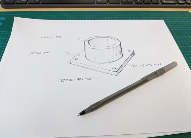
Figure 1: Ideation on paper
2: Organize your features
Be honest...you don't do this. Especially if you’re one of the only engineers/designers in your company. Because if there are any changes to be made to the model...you’ll be the one making them! However, if your work involves collaboration with many designers/engineers, it is best to name your features accordingly. There are 2 main reasons:
- It will help you quickly identify features that are distinct and important. Especially when you're creating multiple bodies and merging them. Once you get deep into this type of modelling, making any change can be scary!
- If any other engineers/designers need to alter or change your designs, they will thank you a million times over because you’ve made their lives a whole lot easier. Think of it as writing comments in software code “This is the master sketch” “Base” “Mounting holes” etc. Make it clear to the next person viewing your model what your thought process was when making the part.
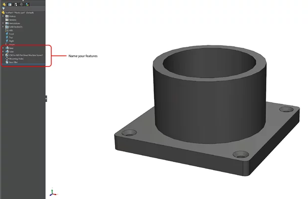
Figure 2: Naming Features
3: Model from the origin
This is a simple and easy one. Most CAD modelling programs use the XYZ planes. Whenever possible, use the center of those planes to create parts. It’ll make assemblies much easier. Whenever we have to cut out port openings in metal or plastic, we always use the center of the component and a reference for the opening. This makes it much easier to modify for tolerances and mating connector openings. However, this might not always be the case if you use the top-down modelling method, where you model directly in the assembly. The point of origin is now in the master assembly and not within the part itself. It has its pros and cons.
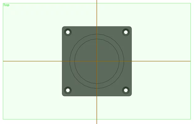
Figure 3: XYZ planes
4: Manufacturing process
This one is easier said than done because it will come with experience. Understanding how a part is made will influence the way you model. Go visit an injection molding facility to understand the process to make plastic parts. Make a note of the do’s and don’ts.
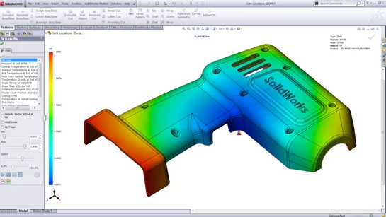
Figure 4: Injection Mold Optimization (Image Source)
Go see your local metal or CNC cutting supplier to see how metal is formed, how to cut, bend and weld metal. If you are fortunate enough to go ask the people making the parts “Hey, how can I make your life easier when I make this part?” There will be no shortage of constructive criticism or design feedback.
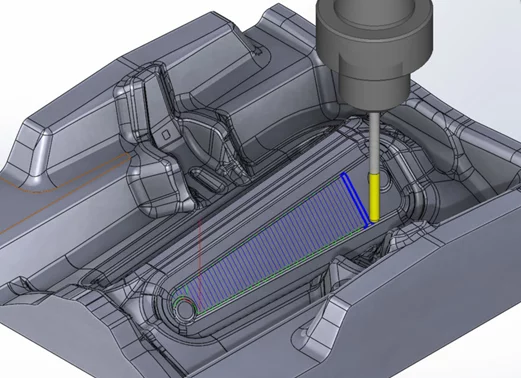
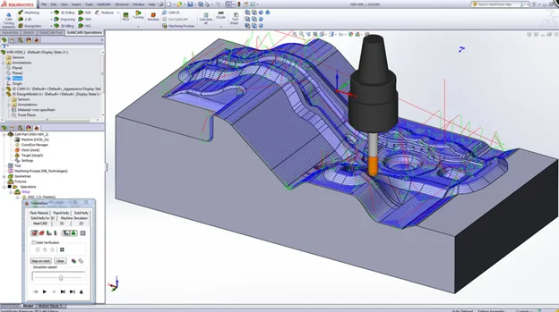
Figure 5: Optimization for CNC Machining (Image Source)
Bonus tip: Try to make your assemblies and sub-assemblies as someone would install or manufacture it. For example: If I have a plastic part with molded inserts, we will make that as an assembly by itself. Afterwards, that assembly will become a sub-assembly of my final assembly.
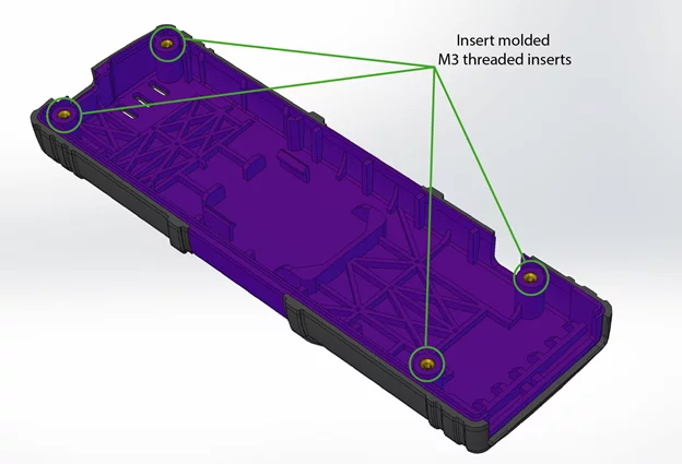
Figure 6: Assemblies and Sub-Assemblies
5: Reference sketches
Let’s say you have to align two holes on two separate parts. Easy enough, right? But what if you need to align 12 different size holes on 3 separate parts that are inconveniently different shapes and sizes? A bit more difficult. But there is a trick to making your life easier.
Edit the parts within the assembly.
If you’re in an assembly, you can always right-click/edit part to draw on it and reference other parts within that assembly. Like the example below:
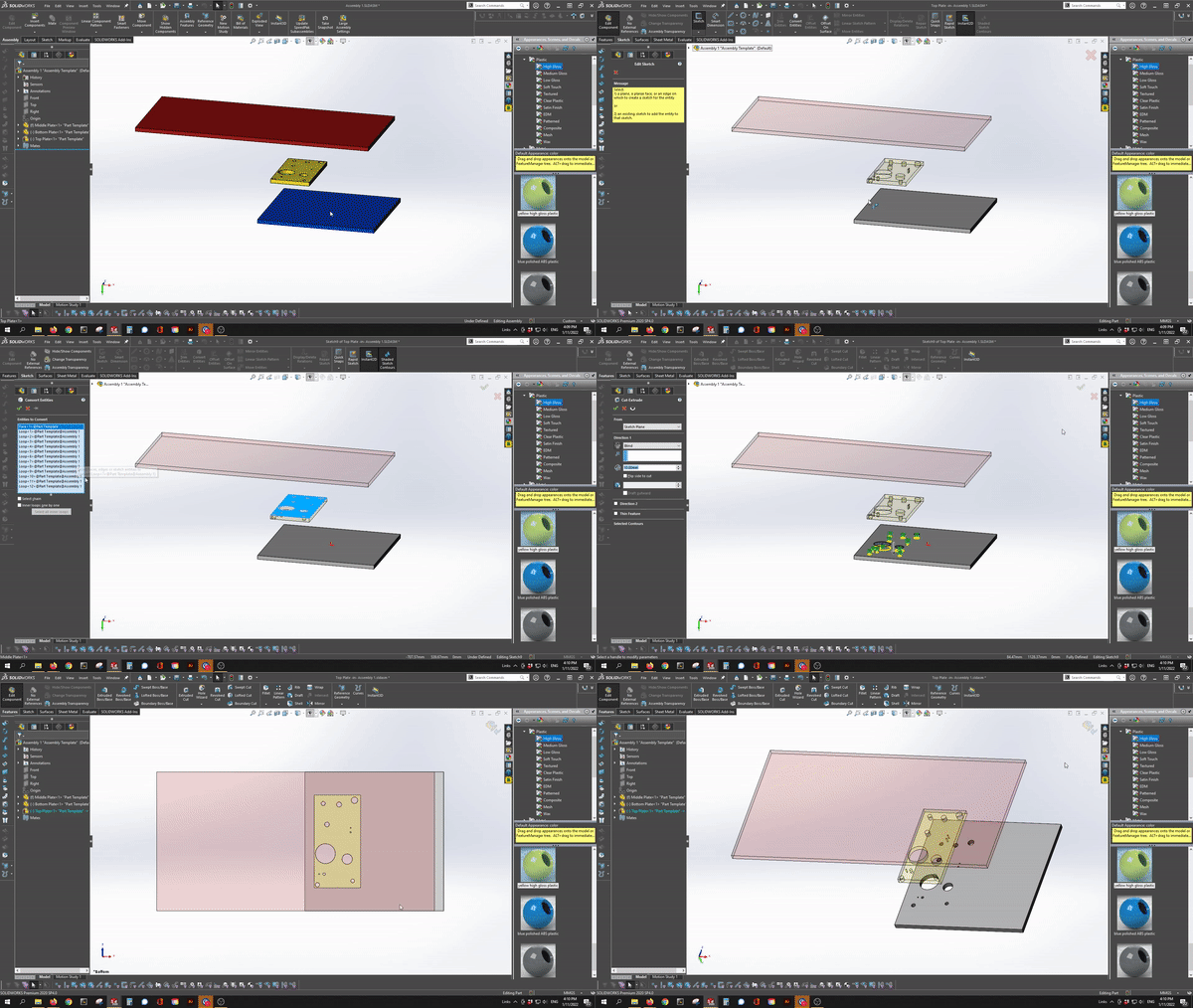
Figure 7: Reference Sketch
So I can very quickly align all these different sized holes within the assembly without having to go back and forth between parts and individually measuring them.
One strong recommendation for this technique is to go back and properly dimension them afterwards. Having sketches from one part, pointing to another feature from another part can be a recipe for disaster. Especially when it comes to editing the parts.
When editing a part within an assembly, make sure to go back and remove the constraints and correctly dimension the part. There’s nothing worse than moving a part with external constraints and opening the assembly to a whole bunch of broken links.
6: Drawings
Design your title block in your drawing to automatically populate all the required information related to the part. This may seem like an easy and obvious one, but it will save you lots of time rather than manually inputting all the data. Define the property tab builder for what works best for you. What information do you want in there? Material? Price? PN? Vendor? For us, currently, we have this information in our property tab. (See image below)
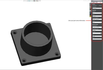
Figure 8: Property Tab Builder
And once we create the drawing, it automatically populates the title block.
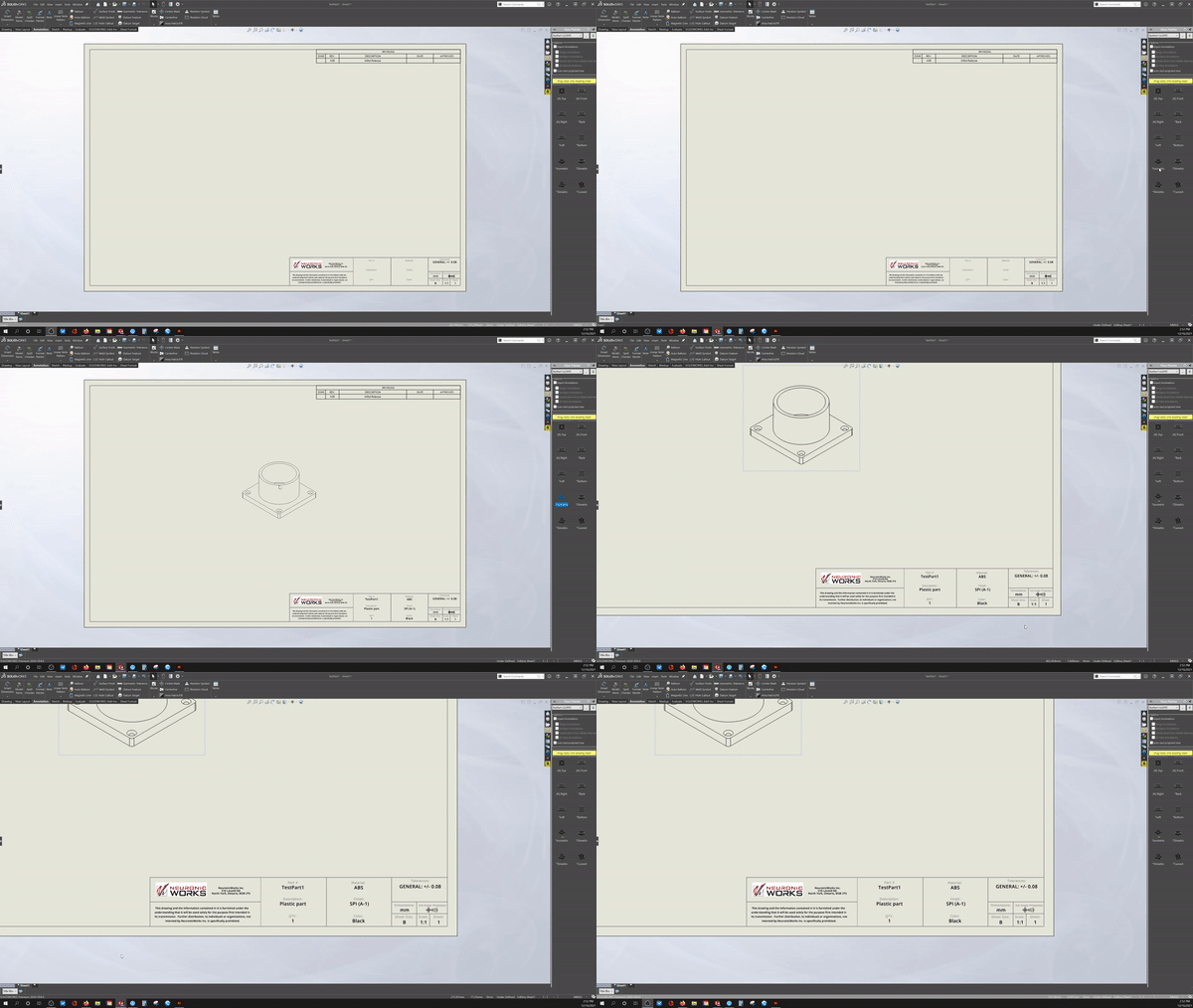
Figure 9: Auto populate Title Block
7: Drawings #2
Keep the drawings clean and simple. There are a few trains of thought on this. Certain engineers love having one drawing with all the required information on the sheet. Fewer sheets mean less paper to print and to review across multiple pages. However, the drawing can become very busy very fast. If you have lots of information to convey in an 11”x17 sheet, it can get overwhelming. Others rather have the information spread out over multiple sheets. This gives the drawings room to breathe and makes it less busy so you can focus on specific details. On the flip side, you have to use multiple sheets to contain all the necessary information.
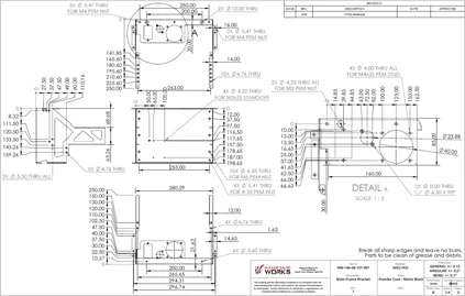
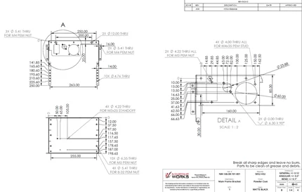
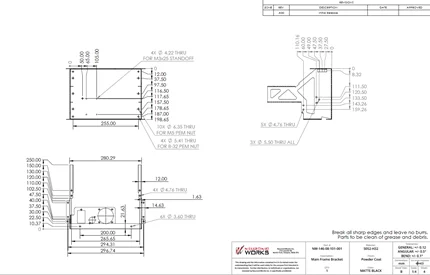
Figure 10: Comparison of sample drawing in one and two separate pages
8: Define your sketches
There’s no greater sight to see than this!
Keep all your sketches fully defined! I know it’s tempting to cut corners and dimension what you need and forget the rest - but it is not a good practice to do so. Keeping all your sketches defined will allow you to make specific modifications to your sketch without throwing the entire sketch out of whack! Take the time to carefully dimension your sketches, and you will have much better control of any future alterations to the part, and it will save you time when dimensioning your drawings.

Figure 11: Define Sketches
Once you create a drawing of the part, whatever dimensions you put on your sketch will magically appear in your drawing. Bam! You’re done!

Figure 12: Auto Dimension
9: Take advantage of the hole wizard
When I first started in SolidWorks, I never used it. It seemed “data-entry-y” to me. Too many parameters. Why can’t I just create a hole and just extrude a cut? So much easier….right? Not so fast.
I only started using the hole wizard within the last 3 or 4 years. And I should have started way before that. You live, you learn :)
There are two major benefits of the hole wizard.
- The parameters for the holes are already created for you! If you want to use a countersunk screw in a hole in your enclosure, just click on the countersunk option, and click where you want to put them. There’s no need to extrude a circle cut and chamfer the edges afterwards. That’s too time-consuming. And what if the hole needs to change from an M3 countersunk screw to an 8-32 Pan head screw? With the hole wizard, it’s a matter of a few clicks and you’re right back on track.

Figure 13: Hole Wizard
- Toolbox.
Throughout my experience, people either love or hate the toolbox option. The Toolbox consists of an editable library of screws, bolts, nuts etc. The benefit of the toolbox option is that it works seamlessly with the hole wizard. If you drag an M3 screw from the toolbox, onto your newly created M3 countersunk hole with the hole wizard, they automatically mate in place. No more manually mating items together.
Figure 14: ToolBox
10: Lose the threads
If you have a big assembly with lots of screws, bolts and nuts. Lose the threads. Your computer will thank you for it! Having a lot of these threads may not seem like a big deal, but they wreak havoc on your computer’s memory and CPU usage. Whenever possible, try to suppress the threads from any screws, nuts or bolts.

Figure 15: Suppress Threads from screws, nuts and bolts